Depth Measurement Challenges - Quality Magazine
Let’s look at some of the part and gage features that may impede accurate depth measurement.
The measurement of the depth of a hole sounds straightforward and simple. In many cases it is. In others, there are design features of both the part and the gage that must be considered to insure an accurate measurement and a properly assembled or functioning part. In past Quality articles (January 2016 and February 2013), we have discussed the basics of using fixed limit cylindrical or threaded plug gages to accurately and quickly inspect the depth of a threaded or cylindrical hole. This time we will focus on some of the part and gage features that may cause problems or impede accurate depth measurement.
Depth measurement on parts is usually a measurement to a specific datum, plane or surface. Variations in the shapes of these features can cause issues with the depth measurement. If the surface is not flat, is radial or has complex geometries or angles, the depth measurement can vary based on the orientation to these features in relation to the gage or gaging surface. When this occurs, it is critical to know the exact surface or plane the depth is required to be measured from to qualify the depth. Figure 1 shows a sectioned or cut part view of a few of these challenges.
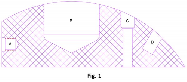
Figure 1 shows a sectioned or cut part view of a few of these challenges.
Hole A is a threaded hole with a counter bore. Hole B represents a hole with a large radius in the bottom. Hole C is a hole with two internal diameters connected by a transition chamfer. Hole D is similar to a blind hole that may be drilled or formed. Holes A and D are shown with the typical drill point. I will let the cutting tool and molding experts weigh in on the various ways these holes may be generated. The key point is that each may have special considerations due to the purpose, function and shape of the part.
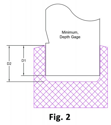
In Figure 2, you see Hole B with a Go cylindrical plug gage inserted. Please note that the bottom of the gage stops at the (D1) depth and the notch is still visible on the Go gage. If the hole has D1 as the defined depth, the hole needs to be made deeper to pass the minimum notch on the Go plug gage. The notch on the gage represents the minimum depth of the hole. The notch on the gage must go below the surface of the part for the hole depth to be in tolerance. If the radius is due to a worn cutting tool, the gage is working correctly and failing the depth of the hole for not meeting the designed minimum depth of either (D1) or (D2).
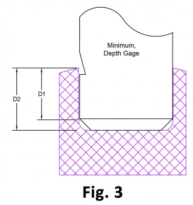
If however the part specification indicates (D2) as the minimum depth of the hole and the radius is part of the design, the hole may be in tolerance. The gage is prevented from going deeper by the radius in the bottom of the hole. The Go gage would need to be altered by grinding a radius or chamfer on the end of the gage to clear the radius on the part. Once the gage is able to clear the radius, it can now accurately measure the (D2) minimum depth as seen in Figure 3.
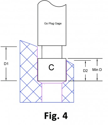
Holes drilled in to angular or radial surface can create other measurement challenges. Hole C, in Figure 4, illustrates some of these issues. Identifying the measurement plane is critical to insure an accurate depth measurement. In this illustration, both (D1) and (D2) may be the minimum depth depending on the product and drawing requirements. If the draftsperson simply uses a leader with an arrow, stating the hole is ½” diameter and ¾” deep, which plane do we measure the ¾” deep dimension from, (D1) or (D2)? Defining this measurement plane can be the difference between a product that passes inspection and one that fails. If (D1) is the minimum depth, the hole is in tolerance. If (D2) represents the minimum depth, the hole is out of tolerance. The hole is not deep enough.
You will note in this illustration we used a gage with a depth groove instead of a depth notch. The depth notch, only ground on the side of the gage (or at 180° in the case of Go and No-Go notches), may not be visible to the user due to the angle or radius of the part. It may also offer a subjective measurement. One inspector could see the depth location differently than another when inspecting the same part. The depth groove provides a full 360° view of the measurement plane on the gage. When the gage with the depth groove is inserted into the hole, the groove creates an unbroken depth measurement plane that is visible to any inspector or user. This generates better measurement repeatability between inspectors as well as the manufacturer and the customer.
Holes B and D are blind holes. These holes do not have any extra space for cutting fluids, foreign material or even air to escape when the Go plug gage is inserted. Parts that have close tolerance hole diameters and are blind as well can cause false depth measurements. In these parts, pressure may be caused by the insertion of the gage into the hole. If the hole is manufactured to the low side of the tolerance, cutting fluids, oil or air can become trapped in the bottom of the hole. The snug fit or the viscosity of the fluids can create pressure that prevents the gage from reaching the bottom of the hole and measuring the depth accurately. (Clean parts are assumed, for this discussion. Measuring dirty parts or even defining what is clean or dirty is a hotly debated topic for another time.) A simple ground flat on the diameter of the Go gage creates a way to alleviate this pressure and allow foreign fluids or gases to escape. See Figure 5. This then allows the gage to reach the bottom of the hole and give an accurate measurement of the depth.
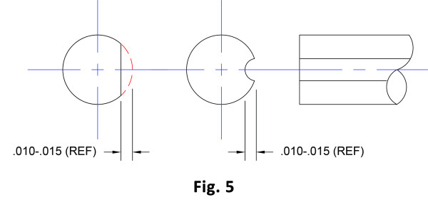
The air flats or grooves on the Go gage pin are not controlled dimensions. They do not serve any measurement purpose. They are a pathway for trapped fluids and gases to escape during the inspection process, allowing the Go plug gage to reach the bottom of the blind hole.
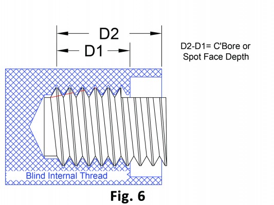
Threaded holes have more features to be aware of when attempting to measure them. In Figure 6, we have an illustration of Hole A with a thread gage inserted. The Go thread plug gage has a notch ground on it to represent the minimum thread depth (D1) for this hole. This gage does not work properly due to the counter bore or spot face above the thread. The counter bore hides the notch on the gage when it is threaded to the correct depth. Depending on the diameter of the thread and the counter bore, the user may be able to see when the notch goes below the first thread. Based on the viewing angle and the visibility inside the hole, the measurement would be very subjective and open to interpretation.
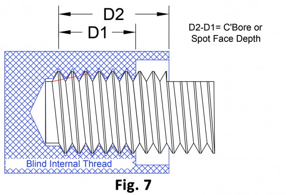
One way to mitigate this is to move the notch on the Go thread plug gage to include the counter bore as seen in Figure 7.
If the gage threads into the threaded portion of the part and the gage notch were below the face of the counter bore (D2), the thread would be in tolerance for the (D2) length. Adding the (D1) length and the measured counter bore depth together equals the (D2) length. This solution is not without some hazards. As with all measurements, we need to be aware of what we are measuring, as well as the stack up of the tolerances. If the counter bore has a tolerance of ±.005” and the thread (D1) has a ±.010” tolerance, this option can work. If however the tolerances are reversed, (D1) ±.005” and the counter bore at ±.010”, this option would not work. The acceptable variation in the counter bore would be translated to the thread depth (D1) measurement. If one part had a counter bore with a +.008” tolerance and another part had a -.007” tolerance, measurement issues can occur. If both parts had a (D1) thread depth of zero tolerance or on size, the .015” variation of the counter bore depth could have the inspector pass one part and fail the other. Yet both parts could have a good (D1) thread depth.
Being aware of the product tolerances and the challenges of the various part design features is one element of accurately measuring the part. Understanding what and how the gage measures the part is the other aspect to consider. Combining the understanding of the part and gage design, tolerance and function are the keys to insuring only in tolerance parts are accepted.
Remember: The part design and tolerances dictate the gage design and tolerances. The gages never dictate the part. The gages only inspect the part based on the part requirements.