Depth Measurement - Quality Magazine
Is the hole too deep, not deep enough or just right?
The measurement of a drilled, reamed or formed hole depth may be inspected in a wide variety of methods. It can be as simple as applying masking tape to a drill or reamer to ensure the hole is deep enough, or as complex as the use of coordinate measuring machines and vision systems. The importance and applicable tolerance of the hole depth will dictate the accuracy and, in many cases, the method that is used to inspect the hole.
|
Tech Tips: Grinding something as simple as depth notches or depth steps on the go plug gage is a popular option. The notches will provide a quick and accurate inspection of the depth and the minimum diameter of the hole, on the same gage. The notches serve as a visual indication of the pass/fail inspection of the depth of the hole. |
Grinding something as simple as depth notches or depth steps on the go plug gage is a popular option. The notches will provide a quick and accurate inspection of the depth and the minimum diameter of the hole, on the same gage. The notches serve as a visual indication of the pass/fail inspection of the depth of the hole. As with all types of measurement, there are rules that need to be applied to ensure the accuracy of the measurement.
|
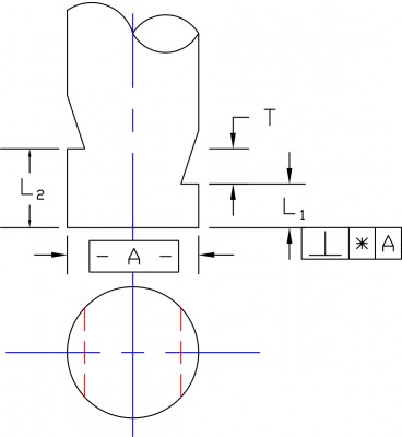
Dimensions: A = Gage Diameter, L1 = Go Depth Notch, L2 = No-Go Depth Notch, T = Depth Tolerance |
Figure 1. Depth Notches
Gage hole diameter and depth
1. Depth notches may be added to cylindrical gages to gage hole depth as well as diameter.
2. Length tolerances from .0005”. Available on plug gage sizes .093” diameter and larger. Perpendicularity (*) = .025T or .0005”, whichever is greater.
Figure 1 shows the typical design of a go gage with a notch or notches added to inspect internal diameter depth. (See ASME B89.1.5-1998 Appendix C) The go plug gage is the only gage that should have notches, in most cases. The reason is simple. The go plug gage is supposed to fit and the no-go plug gage is not. The go gage represents the minimum size of the internal diameter. The go gage is required to pass freely through the full length of the internal diameter of the part for the part to pass inspection. The no-go plug gage represents the maximum size of the internal diameter. The no-go gage is not supposed to fit. If the no-go plug gage enters the hole, the hole is out of tolerance. If the no-go does not enter, how is the notch on the no-go going to measure the depth of the hole in the part?
The notches are ground on the go plug gage to represent the minimum depth (go), the maximum depth (no-go) or both the minimum and maximum depth (go/no-go). The go notch would represent the minimum depth with the notch tolerance being applied, plus. The no-go notch would represent the maximum depth with the notch tolerance applied, minus.
The go/no-go would have two notches representing both the minimum and maximum depth limits. When using go and no-go notches on the go plug gage the notches are ground 180° apart for plug gage diameters over .175” diameters. When the diameters are smaller than .175”, the notches are ground 90° apart. This is done to prevent the manufacture of the notches from weakening the plug gage and makes the notches more visible. Both the 180° and the 90° apposed notches allow the inspector to see both notches at the same time. If both notches are visible, the hole needs to be deeper. If the minimum (go) notch is not visible and the maximum (no-go) notch is visible, the hole depth is in tolerance. If both of the notches are not visible, the hole is too deep.
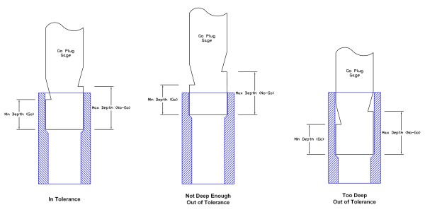
Figure 3.
Angular transitions between two internal diameters can be a challenge to measure, (see Figure 3 above). The chamfer or radius on the end of the plug gage that enters the hole needs to be as small as possible. If they are too large, the radius or chamfer will allow the gage to seat on the transition angle between the two holes.
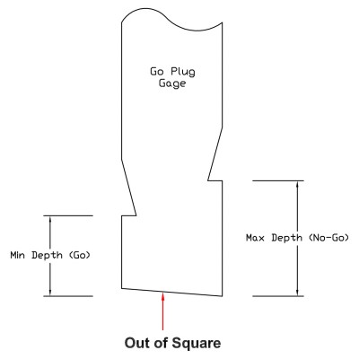
Figure 2.
Another often forgotten feature is the perpendicularity of the face of the gage to the diameter, (see Figure 2 above). The perpendicularity of the face is critical to the accuracy of the notch. If the face is not perpendicular to the diameter, it can cause the notches to be out of tolerance. The same is true for the part. If the hole has a bottom that is not square, the gage will seat at the highest point of the angle in the bottom of the hole. In this case, the gage will correctly show that the hole is not deep enough and cause a failure or re-work.
Radii or chamfers in the bottom of a blind hole can cause problems if not accounted for properly. A large radius or chamfer in the bottom of the hole will prevent the plug gage from reaching the bottom. If you have a large radius or chamfer in the bottom of a blind hole, you may need to have a larger chamfer ground on the plug gage. This larger chamfer will clear the corner chamfer or radii in the bottom of the hole. This then allows you to measure to the bottom of the hole. Attention to how the depth of the hole is noted on the drawing is critical. If the depth of the hole were dimensioned to the top of the radius, the above example would be in tolerance without the large chamfer. The gage stops at the top of the radius, not the bottom of the hole.
There are other types or styles of notches used for depth inspections. The type shown thus far is called a “whistle” notch. Some of the other styles include square or flatted notches and depth grooves.
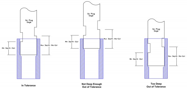
Figure 4.
Square or flatted notches have a square or rectangular flat plunged into the diameter at a specific depth (see Figure 4). They function the same as the “whistle” notch. The bottom of the notch is the gage plane used to measure the depth of the hole. This design can be confusing. Some users question if the top of the square or flatted notch is also a measuring plane. Although it is done in some rare instances, most will use the bottom of the flatted notch as the gage plane.
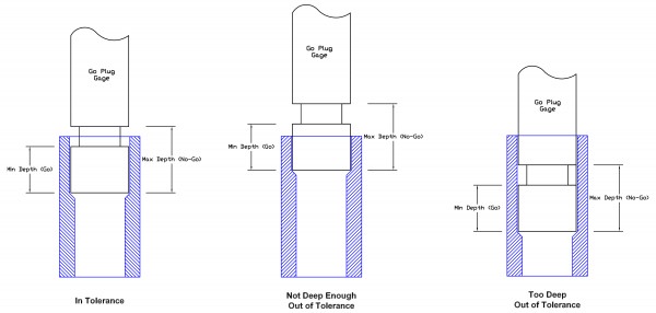
Figure 5.
Depth grooves function as depth inspection tools as well (see Figure 5). These also have advantages and limitations. In the case of the depth groove, the bottom of the groove acts as the minimum (go) depth and the top of the groove represents the maximum (no-go) depth. The nice thing is that you have a groove that goes around the circumference of the gage. The user does not need to rotate the gage in the hole to see the notch as you would with a “whistle” or “flatted” notch. Depth grooves are limited in their width by the ability of the gage manufacturer to produce and inspect them accurately. The minimum width limit for grooves is usually approximately .025” wide. Depth grooves should not be used on small diameter pins. Each gage manufacturer may have slightly different limitations but, generally anything less than .175” in diameter will be a challenge. The other issue with these smaller diameters and grinding depth grooves is the depth of the groove on the gage. If too much material is removed, usually to make the groove visible, the plug gage can become brittle and bend or break. In this situation, a broken gage is better than a bent one. The bent one is no longer accurate.
There are other methods to measure the depth of an internal diameter. The use of step gages, “hard stops,” “flush pins,” Verniers, depth micrometers, CMMs, and even the piece of masking tape on the drill all have their place. The method used to measure the depth of a hole is greatly influenced by the tolerance and the design of the hole. No measuring tool works for every application. The tolerance of the product will always dictate the type and accuracy of the measuring tool to be used. If you are looking for actual measured values, you need to be looking at some type of variable measuring tool. If your job requires a simple pass/fail measurement, it will be hard to beat the simplicity and accuracy of a go plug gage with precision ground depth notches, flats or grooves. Q